01 / THREE DIFFERENT VENTILATION QUESTIONS
During installation.
Inside the building. Under the roof.
Spray polyurethane foam
Closed-cell and other spray polyurethane foams need an installation plan for isolation, outdoor exhaust, cleanup, and keeping occupants, pets, and other trades out of affected areas. Return times depend on the product and conditions. Get the written re-entry and reoccupancy instructions before the job; do not use a universal waiting period.
CFI InsulSmart injection foam
InsulSmart is an aminoplast injection foam used in enclosed cavities. Its published SDS does not specify a fixed timed re-entry or evacuation interval. It does require good ventilation while curing. We establish the access and ventilation plan for the actual job instead of applying the spray-foam schedule automatically.
After the work is complete
A tighter home may need planned whole-building ventilation and a review of combustion-air needs. That is separate from temporary spray-day exhaust. Likewise, soffit and ridge vents serve a vented roof assembly; using spray foam somewhere in the building does not automatically eliminate those vents. An unvented roof requires its own approved condensation-control and insulation design.
Sources: EPA archived SPF ventilation guidance, re-entry guidance, InsulSmart SDS, §7, and DOE / PNNL roof guidance. Use current product instructions for the installation.
02 / TWO TERMS THAT ARE NOT INTERCHANGEABLE
Ignition barrier
or thermal barrier?
| Protection | What it means for your project |
|---|
| Thermal barrier | A prescribed covering or tested assembly that delays heat reaching the foam and meets the applicable fire-test conditions. The phrase “15-minute thermal barrier” is not a 15-minute fire-resistance rating for the whole wall or building. |
|---|
| Ignition barrier | A different level of protection permitted for certain limited-access attics and crawlspaces. It is not a general substitute for the thermal barrier required in an occupied or storage space. |
|---|
| Tested alternative | Specific foam products and assemblies can qualify without a separate prescriptive ignition barrier or with an approved coating. The exact report, application, thickness, and use restrictions matter. |
|---|
What “our foam is tested” actually means
Heatlok HFO Pro has a tested route for certain utility-service-only attics and crawlspaces without a separate prescriptive ignition barrier. This is a conditional product approval, not a physical barrier built into every installation.
Its current report restricts storage, interconnected spaces, and air circulation to other building areas, and sets ventilation, combustion-air, and thickness conditions. The space still needs the required separation from the building interior. A conditioned crawlspace that shares house air needs a separate assembly review.
Tell us how the space will be used. Storage, a stairway, an open connection to a basement, ducts, furnaces, and other ignition sources all belong in that discussion. Storage or regular use can defeat a limited-access exception. A stair or ignition source alone is not the entire code test.
Heatlok HFO Pro: IAPMO ER-0565, §§4.5.1–4.5.2, revised May 19, 2026, valid through March 31, 2027. Michigan framework: 2015 IRC R316, subject to state amendments. Wisconsin uses its own UDC provisions; see below.
03 / CHOOSE THE COVERING BEFORE THE FOAM
Drywall, tongue-and-groove,
or metal paneling?
The answer changes by state and assembly. These examples are for residential work; commercial requirements need a separate review.
| Finish | Michigan / 2015 IRC baseline | Wisconsin / SPS 321.11 |
|---|
| Gypsum wallboard | ½-inch gypsum wallboard is a prescribed thermal barrier. | ½-inch gypsum wallboard is listed. |
|---|
| Wood structural panels | 23/32-inch wood structural panel is prescribed by R316.4. | ½-inch nominal wood structural panel is listed. |
|---|
| Solid tongue-and-groove boards | Ordinary decorative T&G is not automatically a R316.4 thermal barrier. Verify a qualifying exception or tested assembly. | ¾-inch sawn lumber with tongue-and-groove or lap joints is specifically listed. |
|---|
| Metal wall or ceiling panels | Do not assume a thin metal liner is a thermal barrier. Qualifying steel can serve as an ignition barrier in a permitted location. | The sheet-metal exception in SPS 321.11 is for doors. It is not a blanket approval for wall or ceiling liner panels. |
|---|
| Intumescent coating | Use an approved foam-and-coating assembly at its specified application thickness and conditions. Ordinary paint does not qualify. A coating beneath a decorative finish is not automatically approved simply because each material is acceptable elsewhere. |
|---|
Where a finish does not provide the required protection, we can review a listed intumescent coating or another suitable barrier. Confirm the proposed combination with the inspector before ordering finishes or covering the foam.
Sources: R316.4–R316.6; Wisconsin SPS 321.11; product-specific tested assemblies.
04 / CLOSED-CELL FOAM + FIBERGLASS
Flash-and-batt walls:
the balance matters.
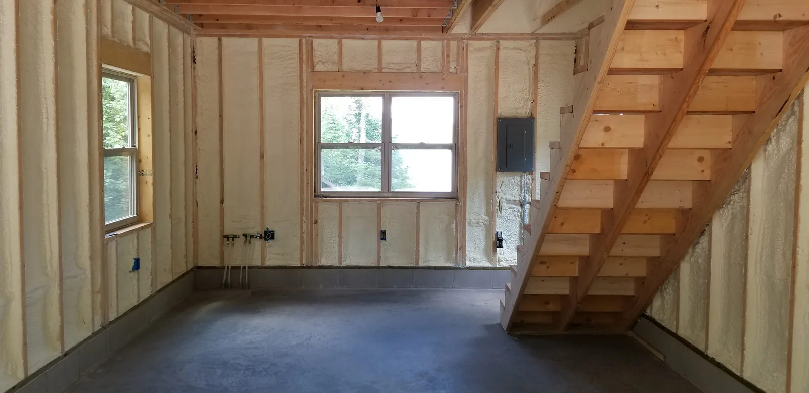
In a hybrid wall, closed-cell foam is installed against the sheathing and unfaced fiberglass fills the remaining interior space. The foam can provide air control and vapor resistance; the batt adds insulation using less foam.
Jesse’s starting recommendation: at least as much foam R-value as batt R-value. In a 2×6 cavity, a common starting detail is 2 inches of closed-cell foam followed by no more than an R-13 unfaced batt. With Heatlok HFO Pro’s listed R-14 at 2 inches, that totals a nominal cavity R-27 when the batt fits at its rated thickness.
Why a thin foam layer is not enough
Adding fiberglass on the room side reduces heat reaching the foam’s interior face in winter. That face becomes colder. Moist indoor air reaching it can condense if the foam fraction, air sealing, and indoor humidity are not suited to the climate. A high combined R-value alone does not solve this.
Closed-cell foam is a vapor retarder at a product-specific thickness. It sits behind the batt in this wall, so this is not the usual arrangement with the vapor-control layer at the warm-in-winter face of all the insulation. The whole assembly needs a deliberate vapor and drying strategy. Open-cell foam does not automatically have the same vapor performance.
Michigan Zone 6 and Zone 7 are different
Michigan’s R601.3 vapor-retarder rule allows a conditional Table R702.7.1 alternative. For 2×6 walls, that table’s qualifying-foam path calls for R-11.25 in Zone 6 and R-15 in Zone 7. Its footnote permits qualifying low-perm spray foam against specified sheathing. Two inches of HFO Pro is listed at R-14, so it does not meet that particular Zone 7 R-15 path. Another compliant design may apply, but the rule of thumb alone does not establish it.
Wisconsin has a separate hybrid exception
SPS 322.38 allows omission of a separate vapor retarder where qualifying spray foam provides at least 50% of the required R-value and has a permeance of 1 perm or less, unless the foam manufacturer requires otherwise. Required air-leakage paths still need sealing. This is a different rule from Jesse’s preference to match or exceed the batt’s R-value.
Avoid accidentally trapping moisture
Do not add interior polyethylene, foil facing, or another very low-perm layer simply because “more barriers must be better.” Layers on both sides can limit drying. We typically call for an unfaced batt in the wall detail above. Vapor control depends on climate, materials, and drying potential; “always on the warm side” is too broad for every assembly, especially below grade.
Sources: Michigan R408.30522a / R601.3; Table R702.7.1 and footnote a; DOE / PNNL wall condensation guidance. Wisconsin has separate vapor-retarder provisions in SPS 322.38.
05 / A CEILING OPTION TO DISCUSS
Batt-and-flash:
less foam, more coordination.
Jesse also uses a ceiling concept that combines an R-38 kraft-faced batt with roughly 1½ inches of closed-cell foam below it. With HFO Pro’s listed R-11 at that thickness, the nominal insulation values add to R-49. Using less spray foam may reduce material cost compared with an all-foam assembly.
This is an assembly to review for the specific project, not a universal installation recipe. Before specifying it, confirm the foam manufacturer’s acceptance of the actual substrate and facing, batt support and uncompressed depth, continuity of the air barrier, facing location, ventilation, and required fire protection. Kraft facing is not an exposed interior finish. This exact batt, facing, and foam combination requires written assembly guidance before we specify it for your project.
Keep air from moving through and around the batts
Fiberglass slows heat flow; it does not itself stop air leakage. Gaps, missing air barriers, wind washing, compression, or poor fitting can reduce performance. Stack effect drives air through leaks, and moving air can carry heat around or through an otherwise high-R layer. The answer is a complete, continuous air-control detail—not simply adding the two label values.
Batts need correct support and fit, contact with the intended air barrier, and protection at exposed edges. An exposed top surface in a properly designed vented attic is not automatically a failure; uncontrolled air movement and poor detailing are the concern.
Sources: HFO Pro R-value table; Johns Manville installation and facing guidance; DOE / PNNL attic air and moisture control. Nominal cavity totals are not whole-assembly performance or code approval.
Technical guidance checked November 14, 2026. Product, permit date, use, and jurisdiction determine the final requirements.